buffa@@essi.fr , diard@@essi.fr , sander@@essi.fr .
See also:
http://www.essi.fr/
 buffa ,
 http://www.essi.fr/
 diard ,
 http://www.essi.fr/
 sander .
[1]The authors may be contacted at the following addresses
by email:
buffa@@essi.fr , diard@@essi.fr , sander@@essi.fr .
See also:
http://www.essi.fr/buffa ,
http://www.essi.fr/diard ,
http://www.essi.fr/sander .
Michel Buffa, Franck
Diard, Mats Persson , Peter Sander
Laboratoire I3S, 06903 Sophia-Antipolis cedex, France
 Linköping University, S-581 Linköping, Sweden
In this paper, we present the Virtual Diver project, work conducted within the Images group at the CNRS laboratory Informatics, Signals, and Systems at Sophia-Antipolis (I3S), in collaboration with the AquaScience Association of the University of Nice - Sophia Antipolis (UNSA ).
The Virtual Diver project arose in response to the needs of marine biologists at UNSA to visualize the benthic underwater environment. In particular, they were studying the colonization by underwater life of artificial reefs, which presents certain challenges, not the least of which is access to the research sites located at depths of up to thirty meters. The reefs must be visited regularly to study the colonization over time, but the depths involved can make this a somewhat hazardous procedure available only to experienced scuba-divers. The emerging technology of Virtual Reality (VR) seemed well-suited to enable ``dry-diving'' onto a computer-created simulation of the reefs, to give a more realistic representation than would be possible just by viewing photographs or videotape.
The goal of the project is thus to create a real-time walk-around system incorporating real underwater imagery. We expect that this will bring a better understanding of the marine biology of the micro-ecosystem for the biologists while providing a demand-driven application for engineering research into VR systems. Off-the-shelf VR technology is not suitable, as the fundamental premise of the project is the visualization of ``what is really there'' rather than the creation of a synthetic world either ab initio or as the result of computer simulation. Nor is the project strictly of the ``3-D reconstruction from a sequence of (stereo) images'' variety [4,21,12,20] as the structural geometric information is already available in the form of CAD models of the artificial reefs. The challenge is to combine the geometry and the photometry by mapping the images onto the CAD model [17] (sometimes refered to as ``augmented virtuality'') and then to provide user-driven exploration of the composite artificial yet realistic world.
The following section briefly describes the underwater reserve of
Monaco and the artificial reefs, §2 is an
overview of the Virtual Diver project and the VR tools we are
developing, §3 describes the methods for
combining the geometric and the photometric information. We present
examples on three types of images: synthetic (in order to explain how
the computer vision algorithms work), images taken in the laboratory
(to evaluate algorithm performance on ``somewhat realistic''
data ), and finally, real images (which
are the eventual goal of the project, but which are much more
difficult as the biology in never ``clean'').
), and finally, real images (which
are the eventual goal of the project, but which are much more
difficult as the biology in never ``clean'').
The paper is not intended to be self-contained, but rather to present an overview of our work in progress. We present some camera-calibration details in App. A however, and the reader interested in the specifics of our algorithms is refered to [8].
The reserve was created in 1976 on the instructions of Prince Rainer III of Monaco. The design and administration are entrusted to the Monegasque Association for the Protection of Nature (AMPN ). The reasons for creating the reserve were the alarming situation in the area due to overfishing, which was endangering the existence of local species [6].
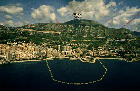
Figure 1: The Underwater Reserve of Monaco.
Courtesy of AMPN (photo: Christian Giordan).
To prevent this disappearance and to produce a zone in which the species still present would be able to reproduce under the most favourable conditions, a protected underwater reserve covering an area of 500,000 square meters, with a perimeter of 2.2 kilometres, and at a depth of from 2 to 38 meters. Inside the protected zone the following activities are strictly prohibited: all forms of fishing from the surface, scuba diving, underwater fishing, all powered navigation, anchoring.
In order to make the reserve as attractive as possible to a wide variety of species, it was decided to sink artificial reefs. A first attempt was made at building them of natural rocks (weighing up to 300 tonnes) sunk at a depth of 25 meters, but the shape of the reef could not be sufficiently well controlled. The AMPN then turned to structures which would be easier to transport and which could be assembled on land.
The solution adopted was to cement together rough concrete
construction blocks such as those used by the building industry. They
have a unit weight of 25 to 35 kg and dimensions of  cm, which makes for easy handling, see Fig. 2.
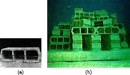
Figure 2: (a) A unit block. The roughness of the walls not only
facilitates easier cementing, but also the attachment of benthic
organisms. (b) A group of blocks as initially sunk underwater.
Courtesy of AMPN (photo: Jean-Marie Moll).
Two different types of artificial reefs were constructed from the rough-wall concrete blocks, the first in the form of a truncated pyramid and a second model in the form of a hollow octagonal structure. The latter type seemed more satisfactory in allowing better light as well as providing a large shaded area in the central shaft, and, importantly for us, the underwater structure is reasonably well represented by a CAD model. Figure 3 shows typical images of an artificial reef in the underwater reserve. Note the difference in the quantity of organisms on the reef between figs. 2(b) and 3 (seven years later).
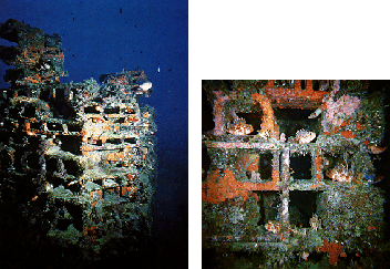
Figure 3: Artificial reef at -28 meters. Courtesy of AMPN \
(photos: Roberto Pronzato, Jean Norbert Monot).
The aim of the project is to allow the highly-interactive exploration of (images of) the reefs, first in 3-D at a given moment in time, and eventually through images collected at regular intervals over time as well. By this we mean a VR system where it is possible to move through a computer-generated world that is an ``exact'' copy of the underwater reserve, created by mapping real world images onto the synthetic model. We want to be able to explore this world in much the same way as one explores the underwater realm when one is actually there, i.e., non-linearly, unconstrained by the path chosen by the wet diver who actually did the videotaping of the reef.
Work on the project can be roughly divided into the following two functionally distinct packages:
As the project is new and initially user-driven, we have concentrated our start-up efforts on determining functionality requirements with the end-users. In this paper however, we present our work on the construction phase. Initially, we are adapting computer vision methods already developed for mobile robotics [3,2,1] to this new problem.
The functionality listed below is the core of the results that have been gathered through discussions with future users. These are the informal demands on how the system finally should work and hence the first building bricks of this research project.
The basic consideration in a VR system is of course movement --- the user has to be able to move inside the computer-generated world in a ``realistic'' manner. Movement in this specific case involves movement in a viscous medium (water) and realistic simulation takes this into consideration, for example by restricting the speed with which changes of direction are allowed to take place.
The crux of the research problem is to map real-world imagery onto the geometry --- once initialized, the CAD model automatically ``wraps itself'' into an uninterrupted sequence of video imagery, see §3 below.
A longer-term goal of the system is to serve as a teaching / reference aid --- the user, interested by some particular organism on the reef, wishes to have access to further information. Designating the organism would bring up a window in which multi-media hypertext-like information would be made available.
Of course the 3-D world has to be built from the structural geometric model and the video images. This involves determination of the camera viewpoint from the image sequences in order to map images onto the given geometric structure. Three-dimensional reconstruction from stereo image sequences with a calibrated camera rig is a difficult problem even in the most favourable of circumstances [9], and the results of currently-available systems seem insufficient for the precise detail needed by the marine biologist end-users. However, in the project we have the advantage that the geometric structure already exists, see Fig. 3, and we can use it to constrain matches with the images as in Fig. 5.
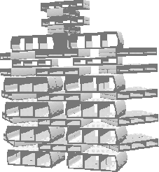
Figure 4: One face of the detailed CAD model of an artificial reef.
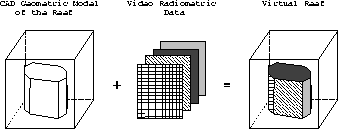
Figure 5: The sequence of video images is mapped
onto the geometric structure.
Initialization is done interactively, then the system determines camera motion from a continuous image sequence and maps the images onto the appropriate pose of the model [15,13]. Several different strategies are available as a function of the grain at which the mapping takes place, e.g., at a coarse level to mosaic whole images onto planar faces of the geometric model (see for example [19,14]), in which holes in the structure are actually images of holes. On a finer level of detail, the geometric structure is used as a ``cookie-cutter'' to select portions of images corresponding only to surfaces of the blocks. The topology of the structure is respected, and the virtual diver will actually be able to penetrate into the holes in the blocks and ``swim'' through the stucture.
Inevitably, the first problem encountered in attempting to recover 3-D information about the world from a stereo image or from a sequence of images is that of determining an accurate model for the camera(s) used - the camera calibration problem. Camera calibration has received much attention in the computer vision literature over the last decade (see [9] for a survey), and common techniques fall into two classes:
Accurate strong calibration is hard to achieve, principally as very good observation of the calibration target is required, and it has been shown that the quality of the calibration decreases as the distance between the target and the camera increases. In addition there are practical considerations which can make strong calibration difficult in some cases. Consider, for example, underwater observation in which it is not practical to calibrate the cameras with respect to a special-purpose reference target --- it may just not be possible to sink the calibration target each time it is necessary to take pictures of an underwater landscape.
On the other hand, weak calibration techniques are still a subject of research and can be somewhat unstable. Furthermore, they do not give explicitely the 3-D position of the camera, which is exactly what we need. Thus, we have decided to use a modified version of the strong calibration techniques (later, we will consider the possible use of weak calibration techniques).
For our application in fact, we have no need of a special-purpose calibration target since we already have available the 3-D model of the artificial reef. Given an image of the reef, the user can select a small set of points (at least six) corresponding to some distinguished vertices in the 3-D model. Using these matches, the camera parameters can be computed, in particular the 3-D camera position (see App. A for more details of the recovery of the camera parameters).
Figure 6 demonstrates the principles involved on a wholly synthetic image (useful for judging accuracy). A cube was modeled and imaged by a synthetic camera with known parameters, and the idea is to recover the position and orientation of the cube from the image. It can be seen that the method performs very well, and this is confirmed quantitatively in table 1 comparing the parameters of the synthetic camera with the camera parameters determined by the calibration procedure.
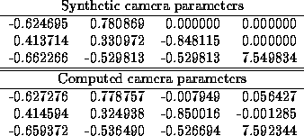
Table 1: Comparison of the camera parameters
of the synthetic camera and as determined from the image.
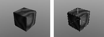
Figure 6: Object corners extracted from a synthetic image,
and the 3-D model superposed onto the object after calibration.
The next level of difficulty is on what we term ``realistic'' imagery, that is, real images but of man-made, generally rectilinear, environments. This is the situation confronted by mobile robots evolving in building interiors, for example. In fig. 7(a) we show the image of a textured box taken by a video camera in the laboratory (the image is intentionally simplistic, we have created a somewhat more elaborate ``artificial artificial reef'' in the laboratory for running more comprehensive tests), and the six features extracted for calibration. Manual selection of these corners can be subject to error, hence we have used an efficient corner and vertex detector [7] which works to subpixel accuracy directly on the grey levels of the image. The user has only to indicate a rectangular zone containing the corner. Very good results have been obtained on these types of images, as in fig. 7(b) showing a close-up of one of the selected corners. Figure 7(c) shows the superposition of the 3-D model onto the image of the object. The projection has been performed using the calibration matrix computed from the features of the image.
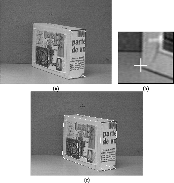
Figure 7: (a) Object corners in a real image.
(b) Zoom of one of the corners. (c) Wireframe model superposed
onto the real object in the image. The camera position was
determined from the calibration parameters computed from the
image.
The real-world case is of course much more difficult than either the synthetic of realistic situation shown above. It cannot be guaranteed that the reefs that have been sunk in the reserve still correspond exactly to the 3-D model of the initial design. Furthermore, the colonization of the reefs by underwater life-forms has altered their shape, e.g., the edges of the blocks that compose the reefs are covered by concretions, and sharp corners can be difficult to distinguish, see figs. 3, 3.1.
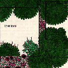
Figure 8: Schematic of block corner showing colonization by
brown and green algae. Courtesy of AMPN .
Once the camera position has been determined relative to the image, a correspondence is established between the geometric structure and the image, i.e., which faces of the model correspond to which regions of the image. This allows us to texture-map the image pixels onto the model. We use a novel technique based on an idea from computer graphics and image synthesis, that of a Z-buffer [8]. A detailed presentation of the algorithm is beyond the scope of this paper (the interested reader is refered to [8]), however we give an example of how it works.
Figure 9(a) shows an image of a textured test object taken in the laboratory with superposed wireframe showing a triangulation of its faces, and 9(b) is the object seen from a different point of view. The crucial difference is that 9(b) is no longer an image taken with the camera from a different position, but a different view of the sythetic object onto which the texture extracted from the image has been mapped.
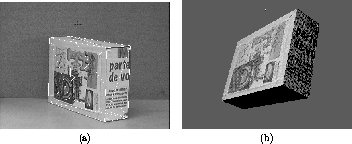
Figure 9: (a) Camera image with superposed wireframe.
(b) Synthetic object with texture mapping.
Figure 10(a) shows the Z-buffer mapping in progress on the end panel of the box, and 10(b) the two triangular textures extracted from the image of the box.
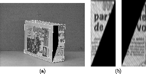
Figure 10: (a) Texture mapping interruptus. (b) Triangular
end panel texture patches extraced from the image of the box.
Figure 11 shows an image mapped onto the reef model of fig. 3.
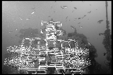
Figure 11: The 3-D model of a portion of the
artificial reef is shown superposed onto the image.
The project is new, we have just completed the design-specification stage in consultation with the marine biologist end-users, and we are beginning implementation of the interface and the navigational package. The low-level system will be based on RenderWare from Criterion Software [18], onto which we are currently building a more easily-useable object-oriented C++ interface [16].
In parallel, and as presented in this paper, we are working on the problem of accurately creating the virtual world by adapting to this new problem technology which we have already developed for 3-D reconstruction applied to mobile robotics [4,3,2].
While user-driven for the underwater environment, we expect that techniques developed will be general enough to be applied to other problem domains where a need for geometric / photometric data-fusion exists, architectural systems and digital terrain mapping to name but two.
The authors wish to thank particularly Jean de Vaugelas of AquaScience for inspiring the project and for videotaping the underwater reefs. David Luquet of AquaScience is responsible for the excellent quality still photographs. Thanks also to AMPN for permission to dive in the Underwater Reserve of Monaco.
We can only provide a brief overview of the essential camera calibration step; the interested reader is refered to [11,8]
In homogeneous coordinates, we write 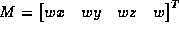 for a 3-D point,
 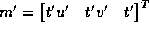 for a 2-D point. Projecting from 3-D
space to 2-D space using the standard pin-hole camera model of
image formation gives the relation
for a 2-D point. Projecting from 3-D
space to 2-D space using the standard pin-hole camera model of
image formation gives the relation
The relation between the projected point  and the image point
 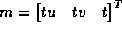 is given by the simple affine relation
Combining eqns. (1,2) gives the relation between 3-D point M and image point m
The parameters  represent the intrinsic
parameters of the camera
represent the intrinsic
parameters of the camera
The camera is positioned at  in world coordinates and
oriented with its axes given in world coordinates by
in world coordinates and
oriented with its axes given in world coordinates by  . Thus
is the mapping from 3-D world to 3-D camera coordinates. The extrinsic camera parameters are the camera position and axes.
Combining eqs. (3,4) gives the complete camera model for image formation
It remains to determine the matrix  . Let w=1 for the homogeneous coordinates of M so that
Expanding eq. e:H matrix and substituting the Cartesian form
of the image coordinates, i.e.,  yields the two equations

in 12 unknowns 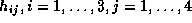 . It is thus
necessary to determine correspondences between 6 points in the image
and on the calibration target, and then to solve for the unknowns by
standard numerical methods. It is then reasonably straightforward to recover the camera parameters from the matrix
. It is thus
necessary to determine correspondences between 6 points in the image
and on the calibration target, and then to solve for the unknowns by
standard numerical methods. It is then reasonably straightforward to recover the camera parameters from the matrix  [11].
[11].
The Virtual Diver, an Architectural ``Swim-Around'' System Incorporating Real Imagery
This document was generated using the LaTeX2HTML translator Version 95 (Thu Jan 19 1995) Copyright © 1993, 1994, Nikos Drakos, Computer Based Learning Unit, University of Leeds.
The command line arguments were:
latex2html -split 0 CES95.tex.
The translation was initiated by Sander Peter on Tue Apr 25 20:03:32 MET DST 1995


